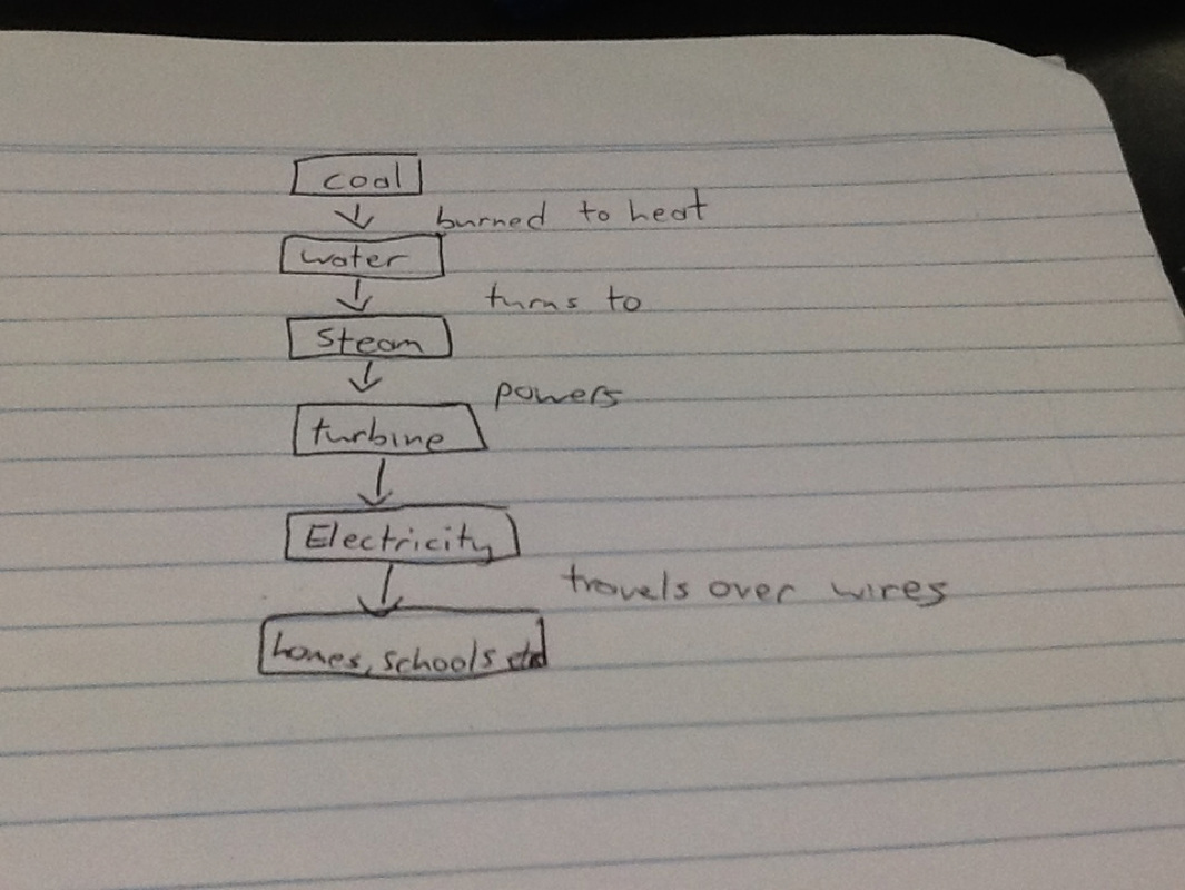
This is a flowchart showing how electricity moves from coal to houses, buildings etc.
0 Comments
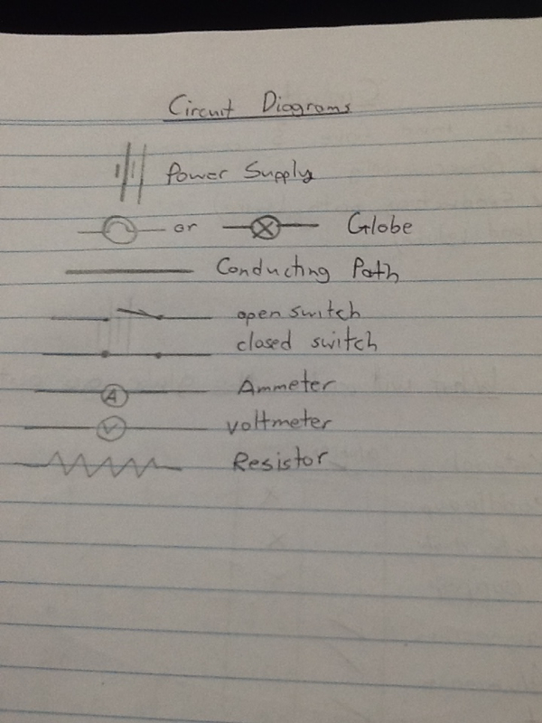
A voltmeter measures the electrical potential difference between two points in an electric circuit.
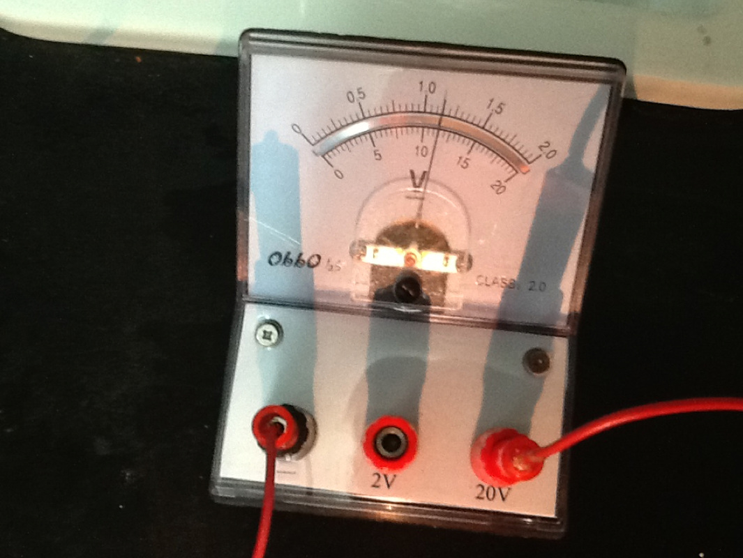
What is the relationship between voltage and current?
Ohm's law applies to electrical circuits; it states that the current through a conductor between two points is directly proportional to the potential difference or voltage across the two points, and inversely proportional to the resistance between them.
Or simply V = I*R
Note that Ohm's law apply only to ohmic materials i.e. Materials which obey ohm's law.
Not all materials follow this V = I*R relationship.
Ref: http://answers.yahoo.com/question/index?qid=20090420163630AAFGtrK
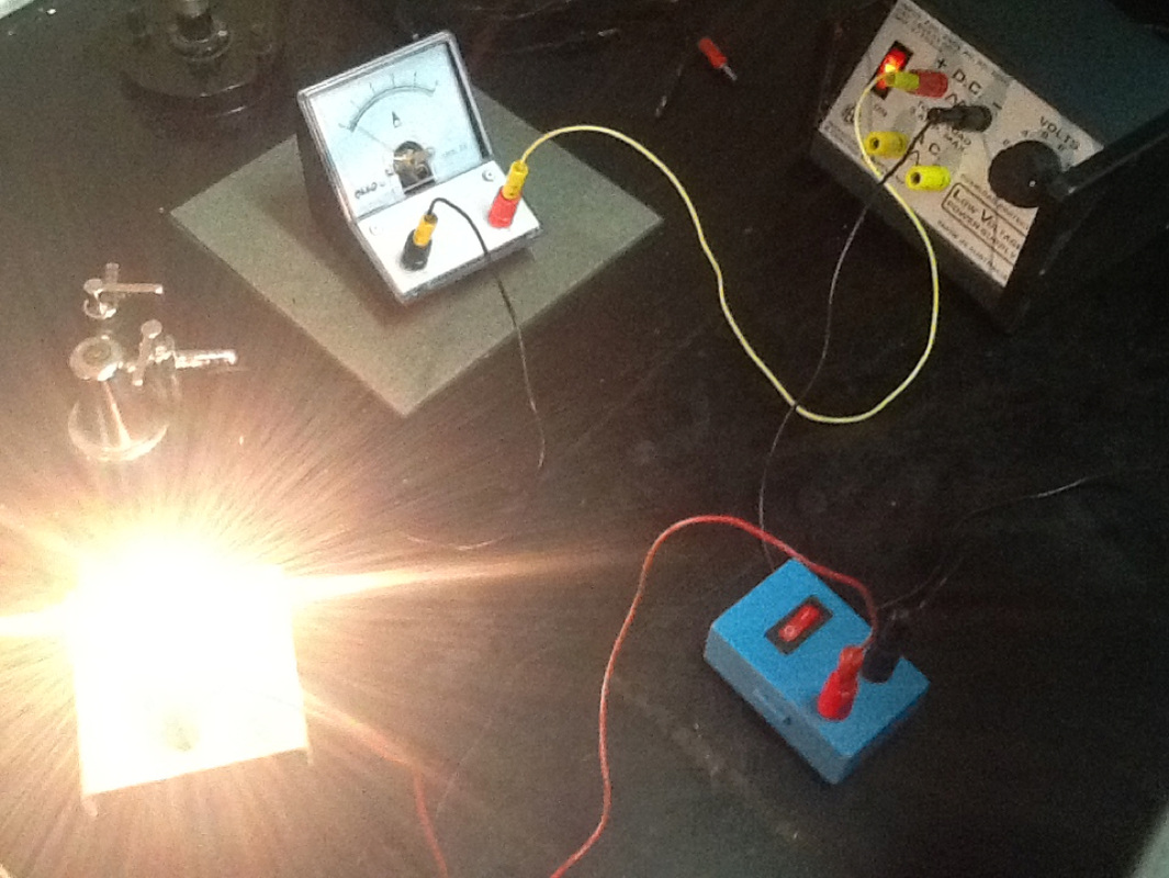
An ammeter measures amperes or flow of current through the circuit.
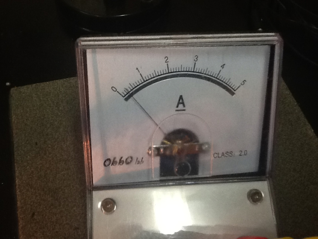
First connect the ammeter to the electric circuit. Ammeters usually have screw connectors either at the top or at the back of it. Now, Connect the wires to the positive and negative screws and tighten it. Now you can see the reading.
Reference: http://how-to.ask.com/other/how_to_read_an_ammeter
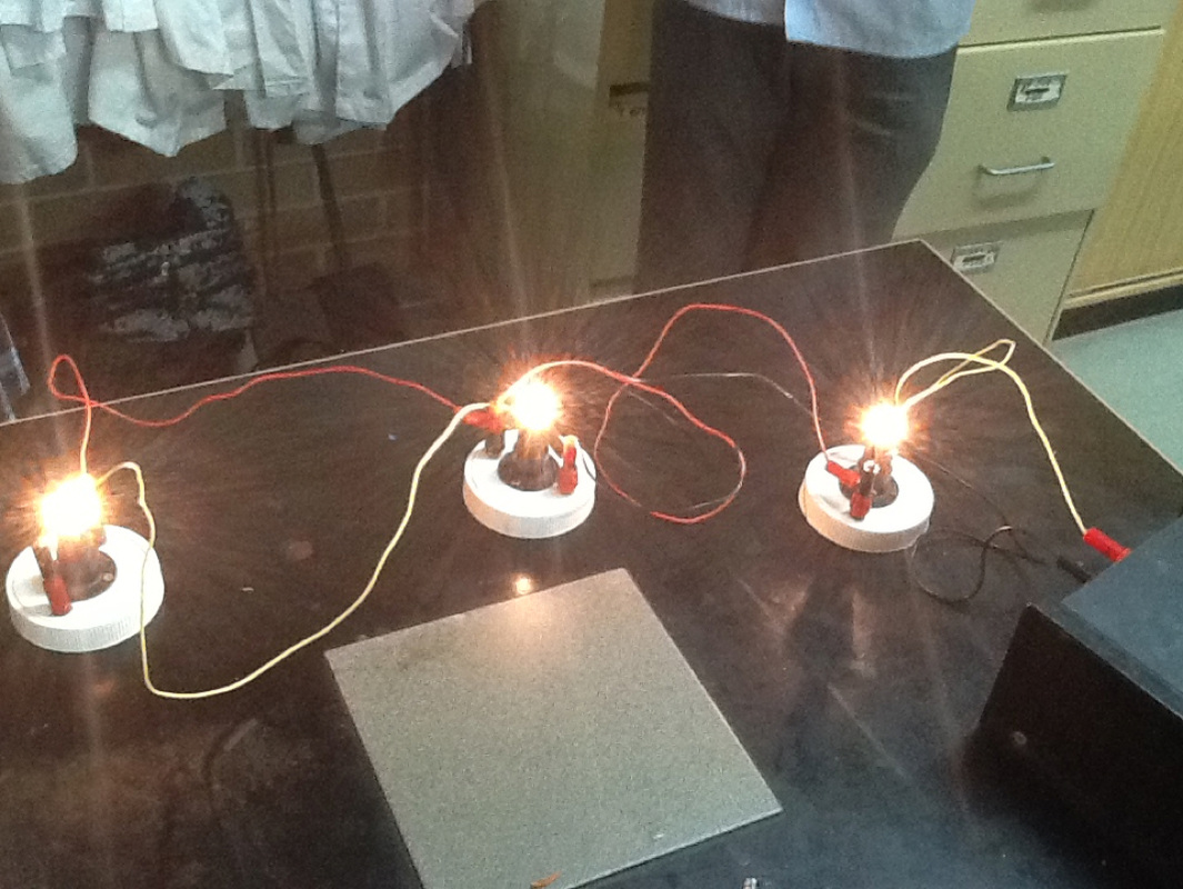
This is a parallel circuit which means that if one light goes out the rest will go out.
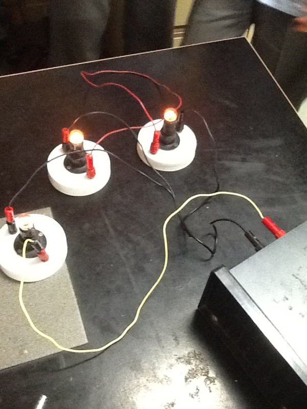
This is a series circuit which means that if one light goes out, the other lights will go out too.
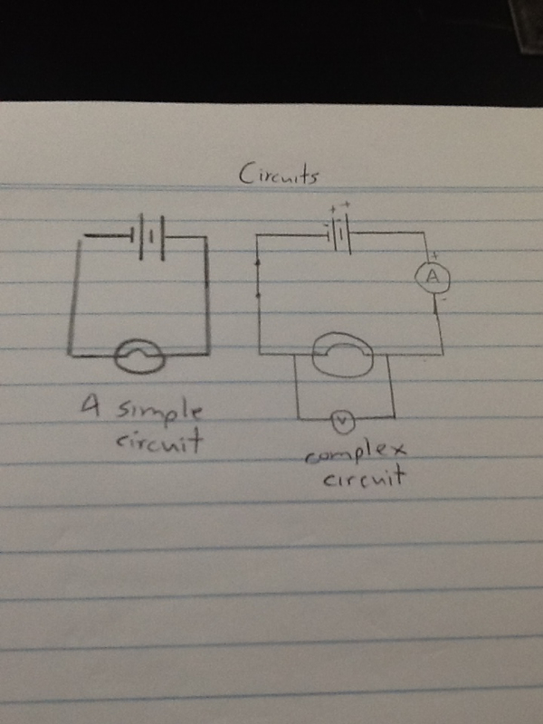
The diagram of a simple and complex circuit.
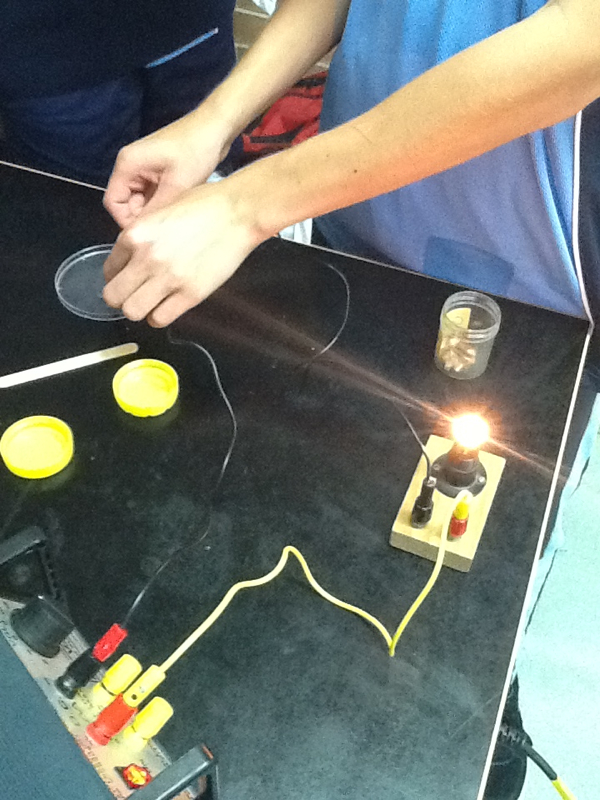
Magnesium being used as a conductor to power the globe.
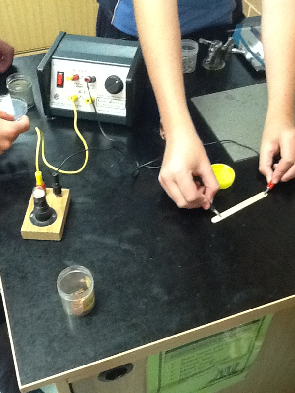
A paddle pop acting as an Insulator and not powering the globe.
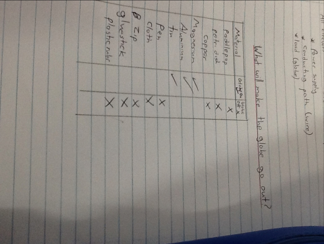
The table of what powered the globe and what didn't.
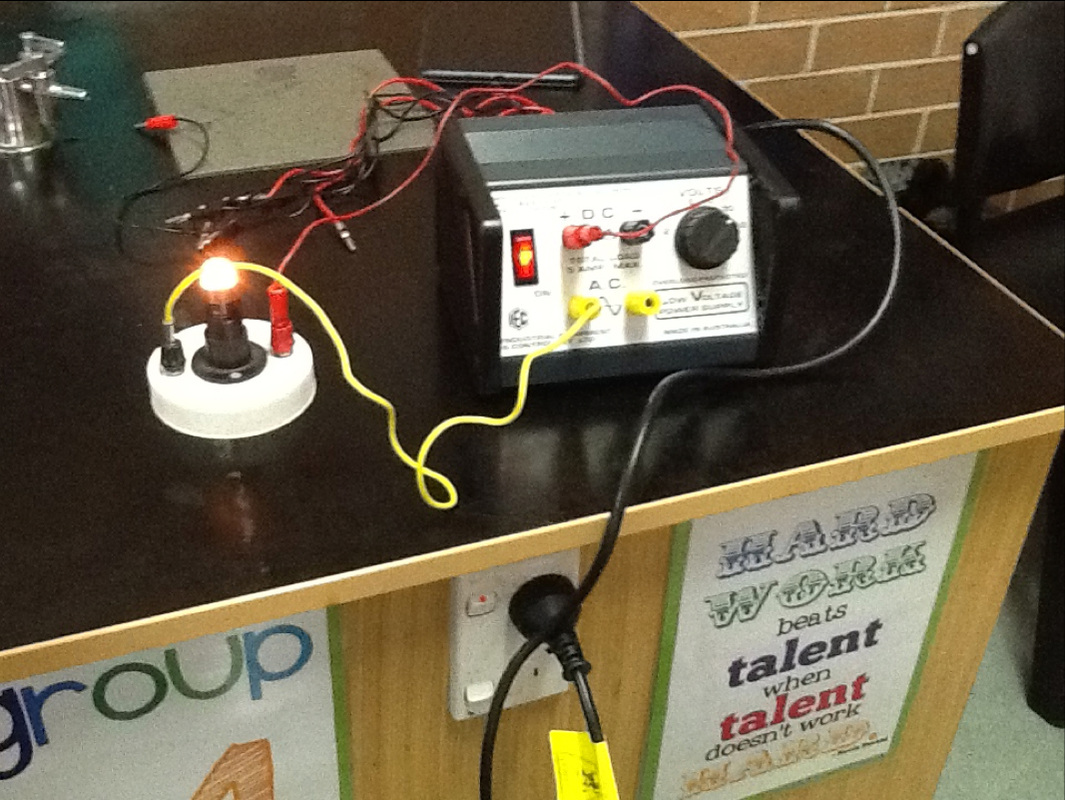
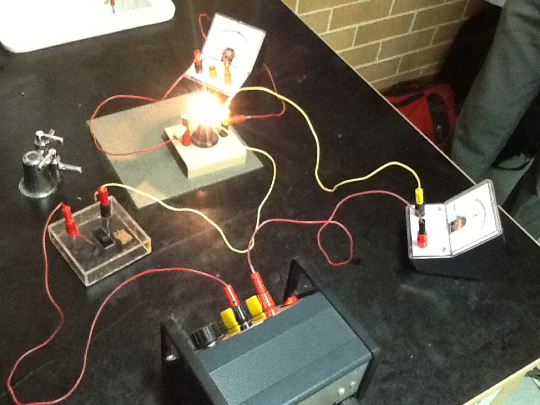
A simple circuit. The three components needed are:
#Power Supply #Conducting path #load This is the start of my science blog. This will be my digital portfolio of all my work.
| ArchivesCategories |
| Josh's Blog |
|
 RSS Feed